


 English
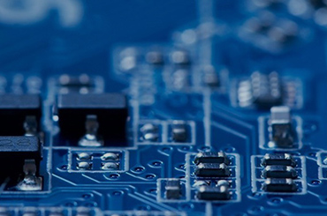
Inductor Coils are essential components in a wide range of electronic circuits, from power supplies and filters to RF and high-frequency applications. Understanding how to test an Inductor Coil is crucial for engineers, technicians, and hobbyists to ensure that the component is functioning properly and meets design specifications. This article provides a detailed guide on testing coil inductors, including various methods, tools, and considerations for different types such as toroidal coil inductors, planar coil inductance, and spiral coil inductance.
1. Understanding the Inductor Coil
An inductor coil, often simply called a coil inductor, is a passive electrical component that stores energy in a magnetic field when electrical current flows through it. The key parameters of an inductor include:
Inductance (L): The ability to store magnetic energy, measured in Henrys (H). A higher inductance coil stores more energy.
DC Resistance (DCR): The inherent resistance of the wire forming the coil. Excessive DCR may reduce efficiency.
Quality Factor (Q): The ratio of inductive reactance to resistance, indicating efficiency at a given frequency.
Self-Resonant Frequency (SRF): The frequency at which the inductor’s capacitance and inductance resonate, beyond which the inductor behaves like a capacitor.
Inductors come in various forms:
Toroidal coil inductor: Wire wound around a donut-shaped core, excellent for high efficiency and low electromagnetic interference (EMI).
Planar coil inductance: Flat coils, often used in compact circuits.
Spiral coil inductance: Coils arranged in a spiral pattern, common in RF circuits.
Conductor coil: General term for coils made from conductive wire, which can be copper, aluminum, or other materials.
2. Preparing for Testing an Inductor Coil
Before testing a coil inductor, ensure you have:
The correct datasheet or specifications from your inductor coil manufacturer.
Proper tools such as a multimeter, LCR meter, oscilloscope, signal generator, or impedance analyzer.
Knowledge of the inductor type (toroidal, planar, spiral) to apply the appropriate testing method.
Also, ensure the inductor is disconnected from any circuit to avoid interference from other components. Testing in-circuit may give inaccurate results.
3. Basic Testing Methods for Inductor Coils
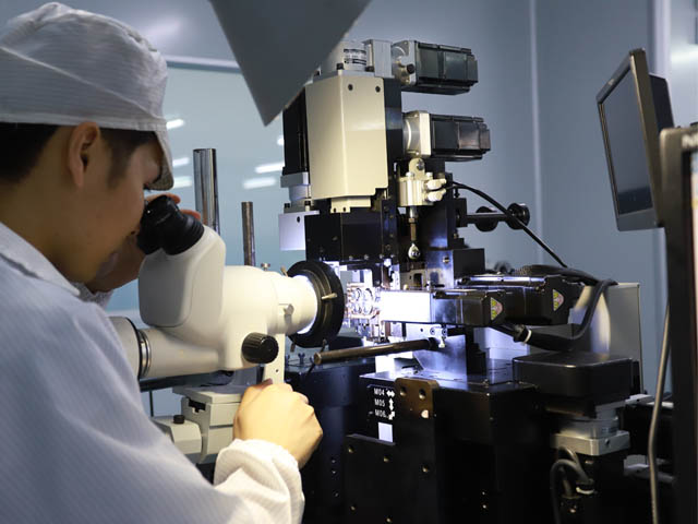
3.1 Visual Inspection
Start with a visual inspection of the inductance coil:
Check for broken or burnt wires.
Inspect the insulation for damage.
Examine the core for cracks or deformities in toroidal or planar inductors.
While basic, visual inspection often identifies obvious issues before electrical testing.
3.2 Testing with a Multimeter
A digital multimeter (DMM) can help perform a preliminary check:
Resistance Test: Measure the DC resistance (DCR) of the coil. Low resistance indicates a continuous coil, while infinite resistance indicates an open coil.
Continuity Test: Use the continuity mode to ensure the coil wire is not broken.
Limitations: Multimeters cannot measure inductance directly and are not suitable for high-frequency characteristics.
4. Measuring Inductance
4.1 Using an LCR Meter
An LCR meter measures inductance, capacitance, and resistance:
Set the meter to the inductance mode.
Connect the probes to the coil terminals.
Read the inductance value and compare it to the specification.
This method is reliable for all types of inductor coils, including toroidal coils, planar coils, and spiral coils. Some LCR meters allow measurement at different frequencies, which is useful for analyzing performance under operational conditions.
4.2 Using a Bridge Circuit
A Wheatstone or Maxwell bridge can measure inductance by balancing the bridge:
Suitable for lab settings and high-precision testing.
Provides accurate readings for spiral coil inductance and planar coil inductance.
5. High-Frequency Testing
For RF applications, simple DC measurements are insufficient. Advanced techniques include:
5.1 Using an Impedance Analyzer
Measures inductance, resistance, and reactance over a wide frequency range.
Critical for testing planar coil inductance and spiral coil inductance in high-frequency circuits.
5.2 Oscilloscope and Function Generator Method
Connect the coil in series with a known resistor.
Apply a sinusoidal voltage from a function generator.
Measure voltage across the coil and resistor with an oscilloscope.
Calculate inductance using the voltage drop and phase difference.
This method is practical for toroidal coil inductors or conductor coils used in switching power supplies.
6. Testing for Faults
Testing for faults in an inductor coil involves checking for:
Open Circuit: Coil wire broken, showing infinite resistance.
Short Circuit: Turns of the coil shorted, which reduces inductance and may overheat.
Core Saturation Issues: For magnetic core inductors, excessive current may saturate the core, lowering inductance.
High-frequency tests often reveal subtle faults that are not visible in DC tests.
7. Special Considerations for Different Coil Types
7.1 Toroidal Coil Inductor
Offers low EMI and high efficiency.
Test using an LCR meter or impedance analyzer.
Ensure the core is not cracked, as this can impact performance.
7.2 Planar Coil Inductance
Flat, PCB-mounted inductors require careful probe placement.
High-frequency measurements are essential to verify inductance at operating conditions.
7.3 Spiral Coil Inductance
Common in RF circuits and antennas.
Use impedance analyzers to measure inductance and quality factor (Q).
Ensure the spiral trace is not damaged or shorted.
8. Tips from Inductor Coil Manufacturers
Leading inductor coil manufacturers provide the following advice:
Always verify inductance at the frequency of operation.
For small 5-axis CNC machine applications or other precision machinery, ensure inductors meet thermal and current handling requirements.
Document all test results to maintain quality standards.
Use shielding or isolation to minimize external interference during testing.
9. Maintenance and Longevity Testing
Regular testing ensures the inductor coil remains within specification:
Check inductance coil periodically in circuits exposed to high currents.
Monitor planar coil inductance and spiral coil inductance for drift over time.
Replace toroidal coil inductors showing signs of core damage or insulation failure.
Preventive maintenance reduces failure rates in critical systems.
10. Conclusion
Testing an inductor coil is an essential process for ensuring circuit performance, reliability, and safety. From simple continuity tests with a multimeter to advanced high-frequency measurements with an impedance analyzer, different methods are available depending on the coil type and application.
Whether it’s a toroidal coil inductor, planar coil inductance, spiral coil inductance, or a standard conductor coil, proper testing ensures that the component meets its specifications. By following the correct procedures, engineers and technicians can maintain high-quality production standards and prevent failures in sensitive electronic circuits.
Working closely with a trusted inductor coil manufacturer ensures access to accurate datasheets, technical guidance, and reliable components for all your testing and production needs.
